公司简介
英国Leysop公司一家超过20年设计经验和制造经验的专业电光器件制造商。其产品包括电光Q开关、电光调制器及驱动、法拉第旋转器、光学偏振器、极化器与衰减器等全系列的产品。
Here you will find information on a wide range of electro optic and passive optical components such as Pockels cells, Q-switches, electro-optic phase and amplitude modulators, high quality calcite crystal polarisers, Faraday rotators and isolators and high voltage drive electronics such as Q-switch drivers and high voltage linear amplifiers for Pockels cell modulators.
Leysop are the only UK manufacturer of electro optic products and have served the international laser community with these vital products for over 20 years in total.
产品列表
Glan-Taylor Calcite Air Spaced Polarizer
 The Glan-Taylor design produces a high extinction ratio polarizer with low reflection losses and a high power handling capability. It is therefore particularly useful for polarizing laser light, with the further advantages that there is no transmission deviation or offset, and that a wide spectral range can be polarized.
Product Specification
| POLARIZER | GT10 | GT12 | GT15 | GT18 | GT20 |
| APERTURE (mm) | 10 | 12 | 15 | 18 | 20 |
| WIDTH (mm) | 11 | 13 | 17 | 20 | 22 |
| HEIGHT (mm) | 10 | 12 | 15 | 18 | 20 |
| LENGTH (± 1.0mm) | 11 | 15 | 18 | 21 | 24 |
| TRANSMISSION RANGE | ------------------- 0.25 - 2.5µm ------------------- | ||||
| EXTINCTION RATIO | 10-5 | 10-5 | 10-5 | 10-6 | 10-6 |
| TRANSMISSION UNCOATED | ----------------------- 88% ----------------------- | ||||
| MAXIMUM BEAM DEVIATION | 3 min | 3 min | 3 min | 2 min | 2 min |
| MAXIMUM OPTICAL POWER PULSED | ------------------- 200MW/cm2 -------------------- | ||||
| MAXIMUM OPTICAL POWER CW | -------------------- 300W/cm2 --------------------- | ||||
LEYSOP supplies GT model Glan-Taylor polarizers with apertures from 10-20mm and larger to special order. Side faces are fine ground as standard, which is adequate to disperse the internally reflected polarization state. Polished side exit faces are provided if required and are recommended for all high power applications. The standard interface angle makes the polariser suitable for operation across a wide wavelength range. Other interface angles can be ordered to cover requirements across the full transmission range of calcite from 0.2 - 2.5µm. please note that because of the absorption in calcite, transmission for most Glan-Taylor polarizers is reduced below 350nm. The main optical surfaces are polished to a flatness of better than l/8 at 0.63µm. Please be aware though that side exit faces are not able to be polished to this same high specification because of the weakness of this face in calcite.
Glan Taylor Polarizer With
Orthogonal Output Side Exit Escape Windows
The Glan Taylor polarizer produces a high extinction ratio with low reflection losses and a high power handling capability. It is therefore particularly useful for polarising laser light. For some applications it is more convenient however to have the S and P polarized beams exit the device at 90° to each other. In this novel design, two specially angled side exit windows give orthogonal output escape beams and the mechanical mount gives a high degree of protection to all four optical surfaces. Another advantage of the angled side exit faces is that these are able to be polished to a much higher specification than the standard Glan-Taylor design.
Specification
| Polarizer | GLBS 10 | GLBS 12 | GLBS 16 | ||
| Aperture | 10 mm | 112 mm | 15 mm | ||
| Spectral Range | --------------- 350 - 2500nm --------------- | ||||
| Extinction Ratio | ------------------- ³ 10-5 ------------------- | ||||
| Maximum Beam Deviation | ------------------- 3 min ------------------- | ||||
| Transmission | --- 88% (uncoated) 93-95% (ar-coated) --- | ||||
| Surface Flatness | ---------------- l/6 @ NaD ---------------- | ||||
| Maximum Optical Power | -- 150W/cm2 (av) - 300MW/cm2 (pulsed) -- | ||||
| Overall Dimensions: | |||||
| Height | 23 mm | 25 mm | 28 mm | ||
| Width | 24 mm | 27 mm | 30 mm | ||
| Length | 40 mm | 48 mm | 55 mm | ||
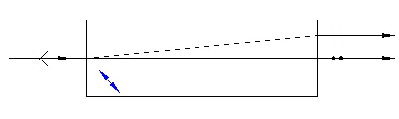
Glan-Taylor Polarizer With Brewster Angled Faces
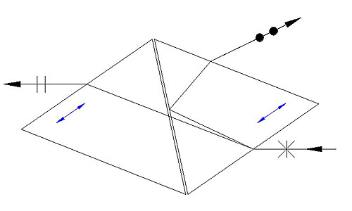
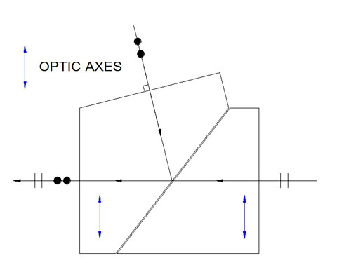
This special version of the Glan-Taylor polarizer is cut such that the P-polarization (extra-ordinary ray) intersects all four optical faces at Brewster's angle, thus ensuring a minimal insertion loss over a wide operating wavelength range. Transmission in fact is approaching 99% for the P-polarization and extinction ratio is exceptional, exceeding that of the more conventional cut Glan-Taylor.
One disadvantage of the Brewster cut Glan-Taylor polarizer, as you can see from the above diagram, is that it produces a reasonably large offset in the beam line. This is typically around 5 to 7mm depending on the size of the device and because of the refraction at the Brewster interfaces, it is also wavelength dependent.
Nominally available apertures are 8, 10 or 12mm and the polarizer can be supplied in a mount if required. As always, Leysop are happy to discuss your precise requirements for these and other components so please contact us.
Glan-Taylor Polarizing Beam Combiner
Glan-Thompson Polarisers
 Calcite Glan-Thompson cemented prism polarizers give the largest aperture field angle product of all calcite polarizer designs and the lowest transmission losses. The cemented interface of the Glan-Thompson however, prevents their use with high power lasers. Applications of the Glan-Thompson include spectral polarimetry and general light polarization and analysis investigations.
In the standard form the length aperture ratio of L/A = 2.5 gives a useable angular polarised field symmetrical about the prism axis of greater than 14° while the long form L/A = achieves over 25°. For UV applications, it is advisable to use the shorter aspect ratio devices because the additional losses caused by the greater thickness of calcite are too high otherwise to be useful much below 400nm
 |  |
| Glan Thompson Polariser | End View Mounted |
SPECIFICATIONS
| Spectral Range | 250 - 2300nm |
| Extinction Ratio | > 105 |
| Beam Deviation | < 2.0 min |
| Transmission AR Coated | 97% |
| Surface Flatness | l/8 |
| Max Power cw | 1.0w/cm2 |
| Type | Clear Aperture (mm) | Ratio L/A | Mount Dia (mm) | Mount Length (nm) |
| GTM 10 | 10 | 2.5 | 25 | 28 |
| GTM 12 | 12 | 2.5 | 25 | 33 |
| GTM 15 | 15 | 2.5 | 30 | 40 |
| GTM 20 | 20 | 2.5 | 40 | 55 |
| GTML 10 | 10 | 3.0 | 25 | 35 |
| GTML 12 | 12 | 3.0 | 25 | 40 |
| GTML 15 | 15 | 3.0 | 30 | 50 |
| GTML 20 | 20 | 3.0 | 40 | 65 |
Rochon & Wollaston Polarisers
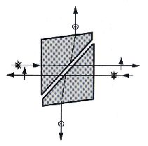
The Wollaston and Rochon polarizers are both beam splitting type devices which rely upon the large birefringence of calcite to cause a difference in the refraction angle at the interface between two differently orientated prisms. In both the Wollaston and the Rochon polarizer the prisms are usually cemented at the interface so the optical power handling is low as a result.
WOLLASTON TYPE
Wollaston prism polarizing beam splitters consist of two equal angle calcite prisms optically coupled with optic axis orthogonally crossed to the direction of propogation. The beam separation of about 20° is then approximately balanced about the input beam axis. The transmission range for cemented prisms of 0.32 to 2.5µm to 18° at 2.5µm.
ROCHON TYPE
In the Rochon polarizer one polarization state is transmitted undeviated through the prism while the orthogonal component is deviated approximately 10°. The straight through component is clearly chromatic while the deviated beam varies from 11° at 0.32µm to 8.5° at 2.5µm.
 |  |
| Wollaston Type BSW | Rochon Type BSR |
Specifications
| Type | Aperture (mm) | Deviation (deg) | Mount Dia (mm) | Mount Length (mm) |
| BSW | 10 | 20° | 25 | 11 |
| BSW | 12 | 20° | 25 | 13 |
| BSW | 15 | 20° | 30 | 16 |
| BSW | 20 | 20° | 40 | 20 |
| BSR | 10 | 10° | 25 | 11 |
| BSR | 12 | 10° | 25 | 13 |
| BSR | 15 | 10° | 30 | 16 |
| BSR | 20 | 10° | 40 | 20 |
Both varieties can be made from optically contacted quartz. The beam deviation is then reduced to only 1° and 0.5° respectively because of the much lower birefringence of quartz compared to calcite. However, the spectral range is increased to 0.2 - 2.0µm.
Beam Displacement Rhombs
This simple device, usually manufactured in calcite, provides an elegant way of separating a beam into its two orthogonal polarization components. A beam entering a block of calcite with its input and output faces cut at 42° to the optic-axis will undergo a maximum displacement (but not angular deviation) of the extra-ordinary ray component. The effect provides a displacement of the centroid of the beam of a little over 1 part in 10 of the propagation length, thus at 1µm wavelength the displacement produced by a 10mm long rhomb will be approximately 1.05mm. Other birefringent materials may also be of use for wavelengths not covered by the transmission of calcite, an example of which would be quartz, but the displacement produced will in general be lower than that of an equivalently long calcite rhomb because of the lower birefringence of quartz.
Specifications
| Model | Aperture (mm) | Length (mm) | Displacement (mm) | Mount Dia (mm) |
| BSC-08-20 | 8 | 20 | 2 | 25 |
| BSC-08-30 | 8 | 30 | 3 | 25 |
| BSC-08-40 | 8 | 40 | 4 | 25 |
| BSC-08-50 | 8 | 50 | 5 | 25 |
| BSC-08-60 | 8 | 60 | 6 | 25 |
| BSC-10-20 | 10 | 20 | 2 | 25 |
| BSC-10-30 | 10 | 30 | 3 | 25 |
| BSC-10-40 | 10 | 40 | 4 | 25 |
| BSC-10-50 | 10 | 50 | 5 | 25 |
| BSC-10-60 | 10 | 60 | 6 | 25 |
Availability
Leysop can provide these components in other apertures and displacements as you require and with or without AR coatings, as you prefer. Components can be provided mounted in protective rings or supplied bare. Please enquire with us for your specific requirements and provided it is possible we would be happy to meet your needs. For example, a 5mm aperture rhomb of length 25mm (nominal displacement 2.5mm), AR coated for 532nm and in a mount would be specified as BSC-05-25-AR532-M
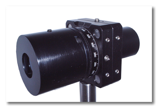
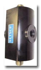
High Power Attenuator Using Glan Taylor Polarisers
Variable attenuators are frequently configured using a combination of a half wave retardation plate and a linear polarizer. Light is input through the retardation plate, a rotation of which produces a rotation in the angle of the plane of polarization as seen entering the polarizer. By Malus' law, the relative transmission of this combination (ignoring other loss mechanisms) is given by the square of the cosine of the relative angle between the plane of the input polarization state and that of the transmission state of the polarizer. This approach relies on the input light being in a well defined linear polarized state and the maximum attenuation will be dictated by the purity of the input polarization state. It is also wavelength dependent by definition as it relies on the retardation plate providing a half wave retardation which of course it will do only for certain wavelengths
This alternative design of optical attenuator uses a pair of high quality Glan-Taylor polarizers and therefore can be used at a choice of wavelengths between 0.35-2.0µm (subject to variations in transmission of the AR coatings). Maximum continuous rating is 200W/cm2 and peak power handling is up to 500MW/cm2 for q-switched pulses (1064nm). If the attenuator is used with plane polarised light the maximum transmission is ~90% and with unpolarised light the maximum transmission is ~40% (lower if un-coated prisms are used for maximum transmission uniformity).
The input polariser is rotated through up to 90o and energy in the side exit beam is dumped onto a light absorbing block. If required the block can be removed and the side exit beam allowed to leave the attenuator. The output polarization state remains fixed for any degree of attenuation as only the input polarizer rotates.
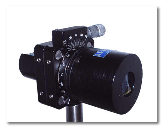
The design of this device has been updated to make it more compact than the original design and also to make it compatible with the popular 30mm cage systems, available from several manufacturers. This also allows for a greater precision in the readout of the rotation angle at which the variable Glan-Taylor polarizer is set. Another benefit of this change is that we can now offer a version with a precision, micrometer driven adjustment of the rotation (in addition to the quick adjustment) that allows for much finer control over the rotation setting, required for obtaining the maximum possible extinction setting. This version is shown below whilst the basic version is shown at the top of the page.
Specification
| Dimensions (see Interface Diagram) |  |
| Mounting | M4 threaded hole / 30mm Cage System |
| Apertures Available | 10, 12 or 15mm |
| Maximum Continuous Rating | 200W/cm2 * |
| Maximum Peak Power | 500MW/cm2 * |
| Operating Range | 0.35 - 2.0µm * |
| Attenuation Range | 0.4 - 60dB |
| Beam Deviation | <3 minutes of arc |
| Wavefront Distortion | <1/4 |
| Input Polarisation State | Any |
| Output Polarisation | Plane Polarised |
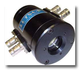
Faraday Optical Isolators
| Type | FOI 5/57 | FOI 5/711 |
| Aperture (mm) | 5 | 5 |
| Wavelength (mm) | 500 - 900 | 900 - 1100 |
| Isolation (db) | ³ 30 | ³ 30 |
| Insertion Loss (dB) | £ 0.5 | £ 0.5 |
| Tunable | Three Ranges 500 - 750, 750 - 850 and 800-900 | ±5° rotation about fixed wavelength |
| Dimensions (mm) | ||
| Excluding Polarisers | 60 dia x 58 long | 75 dia x 75 long |
| With Polarisers | 60 dia x 100 long | 75 dia x 120 long |
In addition to the above 5mm aperture units, we are also able to supply 8mm aperture alternatives (e.g. FOI 8/57 and FOI 8/711) on request. Please be aware though that the cost of the larger TGG rods is disproportionally higher for this small increase in diameter and that larger and heavier magnets are also required. The cost of these rotators/isolators are thus somewhat higher than the smaller aperture models.
Low Order Quartz Retardation Plates
These retardation plates use high optical damage threshold crystal quartz. They are orientated with the optic axis in the plane of the plate and light polarised at 45° to the quartz optic axis is resolved into two equal amplitude components that suffer a relative phase retardation due to their different propogating velocities. Most low orderplates lie in a thickness range of 100-200µm (At 1.06µm a first order l/2 plate is aproximately 182 µm thick). Low order plates are generally used because they are relatively temperature insensitive compared to high multiple order plates. They are also less sensitive to axial misalignment.
Retardation plates can be supplied mounted or unmounted with or without A.R. coatings.
Specifications
| Material | Crystal Quartz |
Surface Quality | 20 - 10 |
| Diameter Tolerance | + 0.00mm - 0.1mm |
| Retardation Tolerance | l/250 |
| Damage Threshold | ³ 1 GW/cm2nanosecond pulse length at 1064 nm |
| Max cw Poweer | ³200W/cm2 |
| Transmission Uncoated | 92% |
| Spectral Range | 220 - 2800 nm |
Standard Sizes
| Type | Clear Aperture | Mount Dia. |
QWP 10 | 10mm | 25mm |
| QWP 20 | 20mm | 25mm |
| QWP 25 | 25mm | 35mm |
| QWP 30 | 30mm | 40mm |
Low order Half and Quarter wave plates having the above dimensions are held in stock and can be supplied coated or uncoated. They are generally available from stock for most common laser wavelengths. All waveplates can be supplied mounted or unmounted. Other dimensions can also be supplied.
Optical Depolarizer Plates
Just as important for many applications as having a well polarized source, it is sometimes necessary to ensure that a source is completely free of any preferred plane of polarization. An example of this is a sensitive spectrometer where varying degrees of polarization will lead to measurement errors. Of course, in nature almost all sources exhibit some degree of polarization, even thermal sources become polarized after reflection from a dielectric surface. Depolarizers are therefore essential items to have wherever a completely un-polarized source must be used.There are two principle methods of producing a depolarization but they operate in different manners and it is essential that the correct type is chosen based on whether the source is mono- or poly-chromatic.
Leysop can provide both types of depolarizer and these are described here.
Lyot Depolarizer
The Lyot depolarizer is assembled from two or more plates of birefringent material, in each plate the optic axis of the crystal lies in the plane of the plate and is orientated at 45° to the axis of the previous plate. The plates are manufactured in a geometric sequence of thicknesses, each plate being twice the thickness of the next thinnest plate. In the simplest case of two plates, one is just twice the thickness of the other. A three plate Lyot depolarizer requires one plate of thickness "t", one of thickness "2.t" and one of thickness "4.t". Depolarization is obtained through the production of varying amounts of circular and elliptical polarization states at different wavelengths. The depolarization effect is poor for monochromatic light as even with a large number of plates in the stack there are only a limited number of polarization states produced. By contrast, a polychromatic source will produce an effectively infinite number of polarization states and thus depolarization is strong, even with just two plates.

Lyot depolarizers can be manufactured in just about any birefringent material, but most applications are covered by either quartz or calcite. Quartz is particularly suitable for applications extending into the ultra-violet and we can provide optically contacted components for minimum insertion loss. For applications where calcite is more suitable, we can provide either cemented or even air spaced components (but calcite is not suitable for optical contacting).
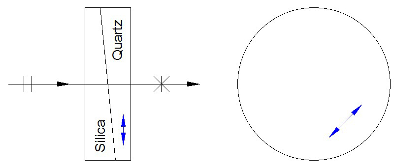
Wedge Depolarizer
The wedge depolarizer is the alternative form which should be used for monochromatic light sources. Again, a thick plate is manufactured in which the optical axis is in the plane of the plate. In use, the optical axis is aligned at 45° to the axis of the incoming polarized light and the thickness of the plate is varied in the plane of the incoming light (a wedge), thus producing a variable birefringence across the aperture of the plate. A second plate of index matching but non-birefringent material is added to the first plate to provide a compensation of the wedge angle, thus minimizing deviation of the beam but maintaining the depolarization. The most common combination is to use crystal quartz and fused silica, usually optically contacted together to enable applications into the ultra-violet.
Availability
Leysop can provide these components in whatever diameter, thickness, number of sections you require (we have manufactured 22 section Lyot depolarizers for one especially critical application) and with or without AR coatings, as you prefer. Components can be provided mounted in protective rings or supplied bare. Please enquire with us for your specific requirements and provided it is possible we would be happy to meet your needs.
Savart Plates
The Savart plate is an extremely useful device, usually manufactured in either calcite or quartz, which is used for the detection of very weakly polarized light for example in starlight.
The beam displacement produced by the savart plate is approximately 0.075 times the total thickness in calcite and 0.0042 times in quartz. When ordering a Savart plate we need to know the material, aperture and thickness required, as well as if AR coatings and a mount are required. For example, a calcite savart plate of aperture 10mm and total thickness 15mm in a mount would be CSP10-15-M. The same part with single layer MgF2 coatings on the outer surfaces centred at 550nm would be CSP10-15-AR550-M.
| Model | Material | Model | Material | Aperture (mm) |
| CSP10 | Calcite | QSP10 | Quartz | 10 |
| CSP15 | Calcite | QSP15 | Quartz | 15 |
| CSP20 | Calcite | QSP20 | Quartz | 20 |
| CSP25 | Calcite | QSP25 | Quartz | 25 |
| CSP40 | Calcite | QSP40 | Quartz | 40 |
| CSP50 | Calcite | QSP50 | Quartz | 50 |
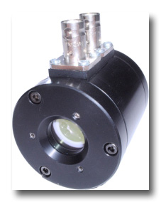
Pockels Cells
Below you will see the variety of different types of longitudinal and transverse Pockels cells manufactured by Leysop for modulation, Q-switching, pulse slicing and pulse picking. If you don't see anything which meets your needs, give us a call. Custom devices are our forté.
Click on the image links for more detail.
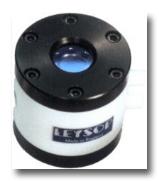
NEW - Ultra-Compact Integrated Pockels Cells
For systems where a large aperture is required but the smallest Pockels cell must be used, the convenience of our new EM508UC is unbeatable. It combines a pre-aligned quarter wave retardation plate and a thin film Brewster plate polarizer for simple operation.
Ultra-Miniature Pockels Cells
This is our next smallest longitudinal mode KD*P Pockels cell, particularly suited to OEM laser manufacture. Aperture is presently limited to 8 or 10mm. Cells are supplied dry with AR coating for maximum optical power handling and are offered for the wavelength range 1047-1064nm. Stud or pin connections are available.
High Power BBO Pockels Cells
Capable of operating at average powers of even hundreds of watts, for applications at the highest average powers there is no better choice than a BBO Pockels cell. The low piezo-electric coefficient also makes it suitable for high repetition rate applications.
RTP Pockels Cells for High Repetition Rate Applications
This is our Pockels cell designed specifically for high repetition rate Q-switching and pulse picking (even to MHz rates) using RTP, selected for its complete absence of measurable piezo-electric resonances. Supplied as an OEM format cell in an industry standard package, a 100kHz driver is also available
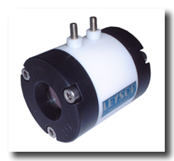
Standard Pockels Cells
This is our conventional range of longitudinal mode KD*P Pockels cells, particularly suited to general laboratory and darkroom environments. Apertures range from 8mm to 20mm and cells can be configured with either 1, 2 or 4 terminals depending on your interconnection requirements. Cells can be supplied fluid filled for low loss or dry for the highest optical power handling
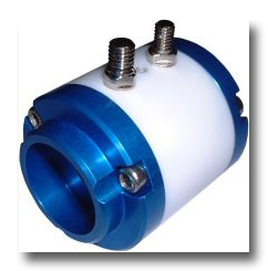
Compact Pockels Cells
This is our more compact range of Pockels cells where a smaller size and simpler interconnect make them especially suited to OEM laser equipment manufacture. Both 8mm and 10mm aperture versions are currently available, but any aperture may be accomodated by this general style of packaging.
Ultra Fast Pockels Cells
This is our special range of ultra fast response KD*P Pockels cells, designed to give the fastest possible rise-times and cleanest responses for the most demanding pulse slicing and pulse picking applications. The aperture is a very useful 6mm diameter, large enough to accomodate most beams whilst being small enough to retain a 150ps time response.
Double Pockels Cells
Double Pockels cells provide an excellent way of halving the drive voltage required by using two crystals to share the work. As well as being available in our conventional Pockels cell packaging, we can also provide compact style devices as well as ultra-fast versions.
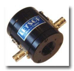
Three Electrode Pockels Cells
For some special applications such as pulse picking and pulse slicing, there are advantages to using Pockels cell cells with three electrodes. These are effectively back-to-back Pockels cells which can then be driven independently to turn on and off the transmission of the optical beam with great precision and flexibility.
Transverse Field Pockels Cells
With the exception of the RTP and BBO cells, all the above Pockels cells use KD*P crystals in longitudinal field mode. Whilst extremely effective devices, there are some applications where transverse field devices are superior choices. These are particularly so where wavelengths are longer than 1100nm, or where small size or low voltage operation are required. Most transverse Pockels cells are made using either lithium niobate or lithium tantalate, both materials of excellent optical quality. The optimum choice will depend on your application, so give us a call to discuss your needs. Custom requirements easily accomodated.
Low Voltage Electro-Optic Light Modulators
Type: EM 200A, EM 200K & EM 200L
EM 200A
This is a low voltage ADP transverse modulator designed to operate at all wavelengths in the visible and is entirely free from piezo-electric resonances. This modulator has a high degree of temperature stability, but where long term d.c. amplitude is required it should be operated in a constant temperature environment. The modulation frequency is not limited by the device characteristics other than by its electrical capacitance and therfore depends on the drive circuit used. Wide band ar-coatings are used on all components.
EM 200K
This is a low voltage transverse KD*P electro-optic modulator designed to give maximum thermal stability beyond that obtained by the ADP type. Its transmission range is extended into the infra-red and its extinction ration is also better than that obtained from its ADP counterpart. It does however display piezo-electric characteristics.
EM 200L
This is a low voltage transverse electro-optic modulator using high damage threshold lithium niobate. It has similar characteristics to the EM 200K with an optical range extended further into the infra-red.
Product Specification
| Model No. | EM 200A | EM 200K | EM 200L |
| Crystal Type | ADP | KD*P | LiNb03 |
| Aperture | 2.2mm | 2.2mm | 2.2mm |
| Crystal Length | 4 x 20mm | 2 x 40mm | 2 x 20mm |
| Half Wave Voltage at 633nm | 220V | 220V | 220V |
| Crystal Orientation | 45°y-cut | 45°z-cut | z-cut |
| Wavelength Range | 0.3 - 1.0µm | 0.2 - 1.2µm | 0.5 - 4.0µm |
| Windows | BK7 | BK7 | Quartz |
| Max. Continuous Applied Voltage | 250 | 250 | 400 |
| Extinction ratio | ³ 100:1 | ³ 200:1 | ³ 200:1 |
| Capacitance | 60pf | 40pf | 60pf |
| Cell Diameter | 40mm | 40mm | 40mm |
| Cell Length | 110mm | 110mm | 110mm |
| Optical Transmission | > 85% | > 90% | > 90% |
| Connectors | ---BNC--- | ||
All modulators are supplied Dry Nitrogen Filled.
Download the Interface Drawing
Electro Optic Phase Modulators
Resonant Phase Modulator: PM50-100 (50 MHz to 100 MHz versions available)
By making the electro-optic crystal part of a tuned circuit, relatively low drive voltages can be used to achieve up to p radians of phase modulation. For the range 50 MHz to 100 MHz the enhancement of the voltage which is able to be applied across the crystal as a result is typically around 10 times that of the 50 ohm input drive.
For the tuned circuit arrangements the drive power required from the source is usually less than one watt.
These phase modulators can currently only be supplied without a drive source.
 | |
| Outline Drawing of Phase Modulator Head |
| Optical wavelength range | 600 - 1300 nm (Lithium Tantalate) |
| Crystal Configuration | Brewster cut or ar/ar normal incidence rod |
| Aperture | 2mm |
| RF Drive power | 2 watt maximum for p radians |
| Tuning range of optical head | ± 15% of centre frequency |
| Voltage gain from tuned circuit | » 10 |
| Input impedance of head | » 50 W |
| Note: These are typical specifications taken from a phase modulator operating at 70 MHz. | |

Travelling Wave Broad-Band Phase Modulator: PM1000 (up to 1GHz available)
For frequencies higher than ~100Mhz, we have found that the enhancement in voltage available from using a resonant circuit is soon lessened to the extent that it is not so effective. We then find that a more conventional modulator is beneficial, however we use a pseudo-travelling wave arrangement to provide a 50 ohm characteristic impedance and also some matching of the optical and electrical phase velocity to maximize the bandwidth. Using this arrangment we have made phase modulators with useful response to ~1GHz. The reasonable availability of moderately high powered (50W) r.f. amplifiers up to this frequency makes it possible to provide a voltage swing of around 140V peak to peak across the crystal which is sufficient to provide a sufficient degree of modulation depth for most applications. The device is supplied without driver or load (the r.f. signal must be terninated in a suitably specified r.f. load)
 |
| Optical Wavelength range | 600 - 1300 nm Lithium Tantalate 200 - 600 nm (ADP) |
| Aperture | 1.5mm typical |
| Characteristic design impedance | » 50W |
| Drive Power | Up to 50 watts |
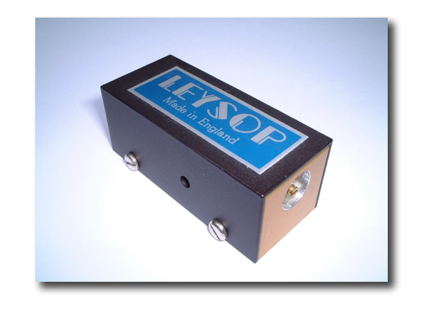
Electro-Optic Deflector Q-Switch
The electro-optic deflector makes an ideal Q-switch for compact, low average power systems. Polarisers are not required and the optical loss can be kept to below 1%. The ability to deflect in a few nanoseconds allows short Q-switch pulses to be produced and high repetition rates obtained. The 1 mm aperture deflector has been successfully used to Q-switch a micro-chip laser at 20kHz while producing 1.5 ns pulse lengths. Leysop can supply the deflector with a miniaturised 1kV driver operating between 0 - 20 kHz. The Q-switch is not liquid filled and does not require accurate alignment.
Deflector Specification
| Aperture | 1mm | 2mm | 3mm |
| Deflector length | 11m | 20mm | 25mm |
| Deflection angle for 1kV drive | 5mrad | 3mrad | 1.5mrad |
| Optical loss ar/ar at 1.06mm | < 1% | < 1% | < 1% |
| Dimensions (mm, excluding connections) | 25 x 25 x 11 | 20 x 20 x 31 | 20 x 20 x 31 |
| Connector | SMA | SMA | SMA |
| Capacitance | 50pF | 50pF | 50pF |
| Switching Speed | Driver limited | Driver limited | Driver limited |
Solid State 20kHz Driver Specification
| Power Input | +9V or +12V @ 0.7A D.C. |
| Output | +900V pulse |
| Nominal Pulse Length | 20 - 100ns, internally adjustable |
| Rise Time into 50pF Capacitor | £10ns |
| Trigger Input | 2 - 5V with 10ns rise time into 50W |
| Repetition Rate | 0 - 20kHz |
| Dimensions | 60 x 60 x 110mm |
| Connectors: Output & Trig. in | SMA |
| Cable length between Pulser and Deflector | 500mm max. |
250 Series High Voltage Video Amplifier
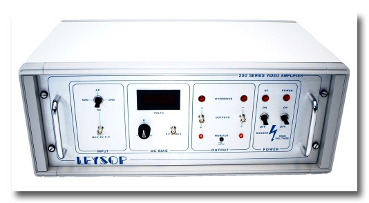
This is a linear Class A output video amplifier with a maximum differential output of 275V over the range d.c. to 7MHz. The two outputs can also be set to ±250V dc relative to each other using a bias control. This facility allows an electro-optic amplitude modulator to be set to any desired light output intensity level for any input signal level. This output bias does not introduce any limit to the signal output range.
The amplifier has been designed to drive electro-optic modulators from the EM200 range where the load is purely capacitive and does not exceed 100pf. The output is short circuit proof.
Specifications
| Signal output voltage range | 275Vdc - 6MHz bandwidth |
| Amplifier Square Wave Rise & Fall Time using 100pf load | < 65 ns (10% - 90%) |
| Bias Voltage Range | +250V to -250V |
| Input Voltage for Full Output | ±1Vdc or 2Vpp., ac |
| Input Impedance | 50 W nominal |
| Cabinet Size (mm) | Height 220, Width 530, Length 340 |
| Mains Voltage | 110/200/240ac 50-60Hz |
| Temperature Range | 0° - 40°C ambient |
5000 Series High Voltage Linear Differential Amplifier
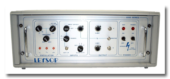
This 5000V series linear amplifier has been designed to drive large aperture electro optic modulators. It consists of two 0.4 - 3.0 kV linear amplifiers that together produce a differential output that can be connected to either side of the modulator. This produces an optical phase change equivalent to the output from a single sided 5000V unit.
The amplifier has a bandwidth of 14KHz and a rise time of less than 5µs.
It incorporates a 1 - 10KHz internal oscillator giving sinusoidal, triangular and square waveforms. For square wave modulation applications the positive and negative excursions of the square wave output can be precisely controlled. This differential drive technique increases the lifetime of the modulator by maintaining a zero mean voltage across its terminals.
Specifications
| Output Voltage Range | 400 - 3000V (each side) |
| Full amplitude Frequency Response | 14 KHz |
| Small Signal Frequency Response (10% Full Amplitude) | 100KHz |
| Rise and Fall Time | 5µsec |
| Signal-Noise Ratio | 50dB |
| Input Voltage | -2.5V to + 2.5V |
| Input Impedance | 1000W |
| Cabinet Size (mm) | 220 (height), 530 (width), 340 (length) |
| Mains Voltage | 110/200/240ac 50-60Hz |
HVP50/80 High Voltage Pockels Cell Q-Switch Driver
| Step Pulse Generator | HVP 50/80 |
| Output Pulse | |
| Voltage Range | 1 - 8 kV |
| Maximum Output current | 200 A |
| Electrical Falltime | < 3 ns |
| Recovery Time | 100 µs exponential |
| Output Impedance | 50 W |
| Maximum on time at maximum current | 200 ns |
| Maximum Repitition rate | 100Hz |
| Minimum Pulse Width | 10 ns |
| External Trigger Input | |
| Amplitude | -3 V to + 3 V |
| Polarity of Leading Edge | Positive or Negative |
| Input Impedance | 50 ohm |
| Minimum Internal Delay | 40 ns |
| Sync Output | |
| Amplitude | ³ 3 V into 50 ohms |
| Jitter wrt High Voltage Pulse | 100 ps |
| Internal Rate Generator | |
| Repetition Rate | 0.1 Hz - 100 Hz |
| Pulse Terminating Load (designed to correctly terminate a 50 ohm coaxial cable) | |
| AC Impedance | 50 ohms nominal |
| Cabinet | |
| Volume (W x D x H) | 330 x 330 x 100 mm |
| Weight | 4 kg |
| Environmental Temperature | |
| Range | 0°C - 40°°C |
| Supply | |
| Mains Voltage @ 50 or 60 Hz | 120 or 240 V ± 10% |
| Power | 50W |
| Enable Input | |
| Removal of a short circuit will prevent operation | |
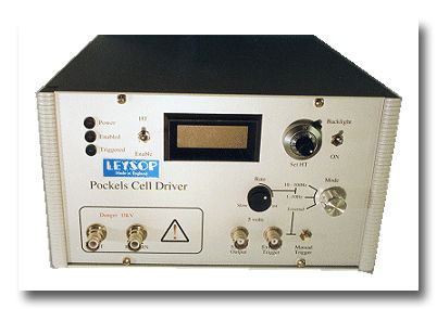
100kHz RTP Pockels cell Q-switch Driver
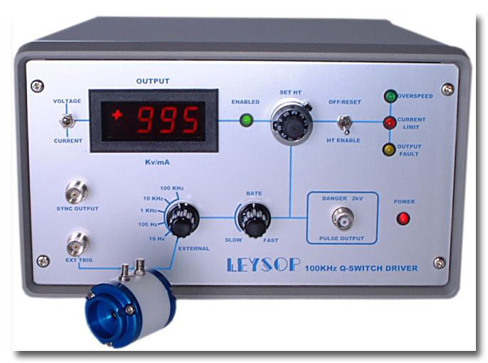
One of the most difficult aspects in dealing with electro-optic devices is the problem of working with high voltages. The majority of electro-optic devices present a capacitive load to the driver which further compounds the problem of finding a suitable driver. However, the relatively low voltage requirements of the transverse field RTP Pockels cell allow us to switch the high voltage at high repetition rates with acceptable power consumption at the driver.
We have developed the driver with the application of continuously pumped sources in mind (rather than flash-lamp pumped for example). For this reason we have not incorporated any facility for varying the delay from the input trigger pulse and the Q-switch output pulse. We have however provided full protection facilities based on internal current limiting to ensure that the demands on the internal HT power supply do not exceed its capability. There is also an internal rate generator for those applications where synchronization to external events is not required and free running use is acceptable.
Safety is of course also paramount and the high voltage output is provided by a safe high voltage (SHV) form of the BNC connector and a matching lead is supplied to connect to the Pockels cell terminals. The HT votage may be set precisely from the front panel to enable the unit to be set for optimum performance at the user's operating wavelength and to allow for the different voltage requirement of the three aperture options available.
Provisional Specification
| Parameter | Value | ||||
|---|---|---|---|---|---|
| Repetition Rate | 0 to 100kHz in five decade steps by internal or external generator | ||||
| Output Voltage | +200 to +2,000V adjustable with visual display | ||||
| Output Pulse | The standard system generates a positive going step function above zero. The generator can also be supplied giving a negative going step from the set HT level down to zero for quarter wave switching | ||||
| External Trigger In | +3.0 to 10.0V min. 10ns f.w.h.m. into 50W | ||||
| Synchronization Output | TTL approx. 30ns after trigger | ||||
| Overload Protection | (1) Repetition rates above 100kHz (2) HT Current above 25mA (3) Output stage fault overload Protection occurs by automatic removal of the HT supply which can be re-instated by the reset switch | ||||
| Power Input | Universal 90 - 265V a.c. 47 - 440Hz via fused IEC inlet | ||||
| Dimensions | 150(h) x 250(w) x 330(d) (mm) Mass: 6kg | ||||
| Step Voltage at End of an Open Circuit 50W Line | |||||
| 50W co-axial cable length | Rise-Time | Flat Top | Fall Time | Maximum Frequency at 2kV | Maximum Voltage at 100kHz |
| 125mm | 5ns | 175ns | 400ns | 80kHz | 1,700V |
| 250mm | 5ns | 160ns | 500ns | 66kHz | 1,500V |
| 500mm | <7ns | 150ns | 700ns | 50kHz | 1,300V |
| 1,000mm | <8ns | 120ns | 1,000ns | 40kHz | 800V |
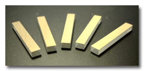
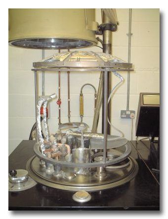
Cutting and Optical Polishing Services
 Leysop employs a number of highly skilled optical polishing technicians, each with many years of experience of cutting and polishing of a varied range of materials. Using mainly hand polishing techniques for the ultimate control of surface finish and figure, optical surfaces may be routinely produced to better than lambda/10 (633nm) and laser finish scratch-dig of better than 10-5. A wide variety of substrates may be polished and our technicians have experience of materials from the softest (ADP, KD*P) to some of the hardest optical materials (ruby, sapphire, germanium). In fact, the water soluble crystals present special challenges for the optical polisher (for obvious reasons)! Our staff however can produce the highest quality laser grade surfaces as demanded by use in high power laser systems.
 We are very happy to offer contract cutting and polishing services to meet your individual needs. Our equipment includes diamond saws, edging grinders for reducing diameters and producing discs and diamond core drilling. All of these are water free for working the specially critical water soluble crystals used in our Q-switches and modulators. These are all backed by our team of highly skilled technicans who can produce precision optical components to your specification. So please give us a call to discuss your requirements. No job is too big or too small. Although much of our work is optical production based, much of our capacity is also available for those small jobs, perhaps manufacturing a special prism in small quantities, or re-working a laser rod which has suffered optical damage. Please try to send us a drawing of what you need if possible; a picture really does paint a thousand words!
Anti-Reflection Coating and Metalization Services
In the course of manufacture of the varied range of Leysop products, we are required to apply both anti-reflection coatings for reduction of Fresnel optical losses at air-dielectric interfaces, as well as metal film layers so that electric fields may be applied to the electro-optic devices. We have dedicated coating vacuum plants for each of these processes to eliminate the risk of cross contamination.
Our dielectric coating rig has both optical and crystal monitoring facilities built into the chamber; thicknesses can thus be monitored against the theoretical curves as well as the practical results. This eliminates errors due to the variable stoichiometry which may occur with some thermally evaporated films.
The majority of our anti-reflection coatings are single layers of a thickness equal to a quarter wavelength of light at the operating wavelength. This simple coating offers good adhesion and high laser damage resistance in most cases. Typically, magnesium fluoride is used for glasses and low refractive index substrates such as calcite, whereas yttrium fluoride is used for higher index substrates such as lithium niobate and lithium tantalate. This offers an excellent match to these substrates and a very low loss can be achieved over quite a broad bandwidth. One major advantage of single layer coatings is that even outside the range of optimum performance, the coating performance will never degrade to the point where the substrate is worse than if un-coated. This however may occur with multi-layer coatings.
For applications where loss is critical and the user only wishes to operate at a single wavelength, we can often deposit suitable multi-layer a/r coatings to offer the lowest possible loss. Please be aware however, that these films are usually more highly stressed than the simpler single layer coatings so may not be suitable for some applications. Adhesion may also be compromised, although this is not necessarily the case.
Please feel free to enquire about coatings for your substrates. We do not claim to be coating specialists, our equipment and practices are largely dictated by the requirements of our own devices (particularly the water soluble XDP crystal isomorphs on which we have vast experience of applying coatings). However, for the simpler requirements we can be more flexible than many of the specialists and can offer the turn around and lower chamber costs that make us more cost effective, especially for experimental and short run work.
Polarising Optics
Glan-Taylor
GT10 10mm
GT12 12mm
GT15 15mm
GT18 18mm
GT20 20mm
GT25 25mm
GT30 30mm
Optical coatings – single layer on input, output and side exit faces, add £50 per face coated. Single polished side exit face, add £90. Double polished side exit face, add £135. Mounted in black anodised cylinder, add £50. Cylinder sizes: 12-25mm ∅, 15, 18, 20-35mm long. 25-50mm ∅, 35mm long. 30-50mm ∅, 45mm long.
Brewster Cut Glan-Taylor Low Loss Polarizer
GTB10 10mm
GTB12 12mm
This polarizer uses a Brewster cut input and output face and an internal interface which is almost at Brewster’s angle for exceptionally low insertion loss. GTB12 12m
Orthogonal Output Glan-Taylor in Mount
This polariser has two side exit windows with outputs orthogonal to main beam axis and is mounted in an anodised aluminium alloy housing as standard.
GLBS10 9mm clear aperture
GLBS12 11mm clear aperture
Including single layer anti-reflection coating.
Glan-Thompson
Short Version Long Version
GTM8 8 x8x20mm GTML8 8x8x24mm
GTM10 10x 10x25mm GTML10 10x10x30mm
GTM12 12 x 12x30mm GTML12 12 x 12x36mm
GTM15 15 x15x38mm GTML15 15 x 15x45mm
GTM20 20 x20x50mm GTML20 20 x20 x 60mm
Calcite Wollaston Calcite Rochon
20°Deviation 10° Deviation
BSW/C 10mm BSR/C 10mm
BSW/C 12mm BSR/C 12mm
BSW/C 15mm BSR/C 15mm
BSW/C 20mm BSR/C 20mm
Quartz Wollaston Quartz Rochon
1°Deviation 0.5°Deviation
BSW/Q 10mm BSR/Q 10mm
BSW/Q 12mm BSR/Q 12mm
BSW/Q 15mm BSR/Q 15mm
BSW/Q 20mm BSR/Q 20mm
Calcite Lyot De-Polariser
CLD10 Two plates 2.5 and 5.0mm thick, axes at 45° 10mm diameter
CLD25 Two plates 2.5 and 5.0mm thick, axes at 45° 25mm diameter
Quartz Low Order Retardation Plates -Mounted (λ/4-λ/2)
For Stock Items Only
Model Clear Aperture Mount Diameter
QWP10 10mm 25mm
QWP20 20mm 25mm
QWP25 25mm 35mm
QWP30 30mm 40mm
High Power Laser Attenuator
HLPA10 9mm clear aperture
HLPA12 11mm clear aperture
HLPA15 14mm clear aperture
30mm Cage system compatible design. Including single layer antireflection coatings.
45° Faraday Rotators and Isolators; 5mm Aperture
FOI 5/57 0.5-0.75μm
FOI 5/57 0.75-0.85μm
FOI 5/57 0.85-0.90μm
FOI5/57BB 0.70-0.90μm Broad Band (90°)
FOI 5/57UWB 0.65-1.1μm
FOI 5/711 0.85-1.1μm
Electro-Optics
Low Voltage Modulators
EM200A EM400A
EM200K EM400K
EM200L EM400L
Transverse Field Lithium Niobate Pockels Cells for Q-Switching
LNQ Crystal 9 x 9 x 25mm, coated for 1064nm
LNQM Crystal 9 x 9 x 25mm, coated for 1064nm
Longitudinal Field KD*P Pockels Cells for Q-Switching
EM508 8mm Aperture
EM510 10mm Aperture
EM512 12mm Aperture
EM515 15mm Aperture
EM520 20mm Aperture
Compact Longitudinal Field KD*P Pockels Cells for OEM Q-Switching
EM508M 8mm Aperture
EM510M 10mm Aperture
EM512M 12mm Aperture
EM515M 15mm Aperture
EM520M 20mm Aperture
EM510C 10mm Aperture
Double Crystal 8mm Pockels Cells for Lower Voltage Q-switching
EM508/2 or EM508M/2 Two crystal 8mm aperture
EM510/2 or EM510M/2 Two crystal 10mm aperture
Special Pockels Cells for Pulse Slicing and Pulse Picking
UPC068 6mm aperture ultra fast (180ps) Pockels cell. Fluid
filled or dry, un-coated crystals at 532/1064nm.
UPC068/2 Double crystal version of UPC068 for half voltage
operation. Fluid filled.
EM505 5mm aperture 3 electrode Pockels cell ideal for use
with two avalanche drivers etc. Fluid filled
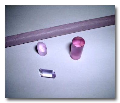
100kHz RTP Q-Switch System (standard AR coating for 1064nm e.g.)
3mm Aperture RTP Q-switch
4mm Aperture RTP Q-switch
6mm Aperture RTP Q-switch
100kHz 2kV Q-switch driver
Phase Modulators
Phase Modulators PM10-/50MHz - Single frequency
PM50-/100MHz - Single frequency
Electro-Optic Deflectors (lithium niobate or lithium tantalate for general applications)
ED1 1mm Aperture
ED2 2mm Aperture
ED3 3mm Aperture
High Laser Damage Electro-Optic Deflector for Q-switching applications
ED1H 1mm Aperture
Electronics
Analogue Drivers for Electro-Optic Modulators
M250 M500
M1000 M2500
M5000
High Voltage Generators for Q-Switching
Please enquire about available options – we can offer many solutions for this and other applications.
900V Pulse Generator for Deflector Q-switch
900V, <5ns rise time, up to 20kHz min. prf